Blog

  • MENG PHOTO-ETCH BENDER

    MENG PHOTO-ETCH BENDER

    MTS-038

    InSCALE MENG PHOTO ETCH BENDER 2

    Some days I feel like Rip Van Winkle, awakening to find the modelling world completely transformed and unfamiliar.

    Getting back into my long lost passion for modelling a couple of years ago, I discovered the extensive use of photo-etch for detailing.

    The T-34 has always been a favourite of mine, so, one of the first new kit acquisitions was the DRAGON T-34/76 Model 1940, complete with what seemed to be a million photo-etch parts.

    At the time, the newly encountered complexity and small parts were overwhelming.

    Fast-forwarding to today, if the kit doesn’t have a million photo-etch pieces, I feel gypped and hard done by. Now I go out of my way to get aftermarket upgrade photo-etch sets.

    To tame the photo-etch spectre, I found proper tools make a world of difference.

    One of my favourite tool brands is DSPIAE. As it happens, MENG also re-brands some of the DSPIAE products. The MENG Photo-Etch Bender differs from DSPIAE in the form of a metal bending blade rather than acrylic.

    Working with larger pieces of photo-etch, especially fenders, a straight fold is important.

    I already have an excellent chromed bender from another company but couldn’t resist the red anodized aluminum.

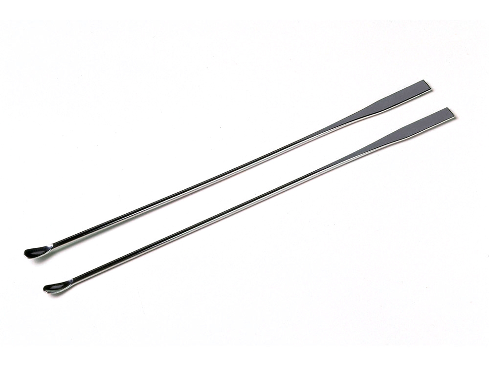
    What I especially like is the heft, the outstanding quality along with the inclusion of an additional small blade for fine photo-etch work.

    If you are into high-quality tools and want one of the best, this is what you want.

    The excellent MENG MTS-038 DSPIAE Photo-etch Bender is available from Hobby Sense.

    InSCALE Tried-Tested-True

  • Red Army Railroad Torpedo

    Red Army Railroad Torpedo

    The Red Army “railroad torpedo” ЖДТ-3 (ZhDT-3) was developed by the Ordzhonikidze Machine Plant of Podolsk in 1935 as a weapon against enemy armoured trains.

    It consisted of a small, two-axle, battery-powered trolley armed with a 495lb (225 kg) bomb containing a 220lb (100 kg) high-explosive charge.

    The ZhDT-3 had a top speed of 37 mph (60 km/h) and a range of about 6 miles (10 km). Production started in 1938 and it was planned to equip each armoured train with five of these devices. While many of these were in service in 1941 at the outset of the war, there is no record of their actual use in combat.

    InSCALE Red Army “Railroad Torpedo” ЖДТ 3 ZhDT 3 Experimental Rail Torpedo

    The solution to non-standard problems is always associated with non-trivial sentences. This fact, as well as the flight of the imagination of gunsmiths, often leads to the appearance of unusual and surprising systems. A vivid example of this design, surprising by the very fact of its existence, appeared in the mid-thirties in the Soviet Union. They became the so-called. railway torpedo ZHTT-3.

    During the First World War and the Civil War, an armoured train proved to be a reliable vehicle with high combat potential. Despite the possibility of moving only on existing railways, such equipment could timely appear in an important area, lead the offensive and support the troops. The only serious threat to armoured trains for a long time was the field artillery, the possibilities of which made it possible to hit protected wagons and platforms. However, armoured trains retained an advantage in the form of mobility.

    In the mid-thirties of the last century, the Red Army command continued to see in armoured trains a serious force that could fully participate in the coming war from both sides of the front. As a result, the army needed some kind of mobile means of defeating such equipment, which had sufficient power. The result of theoretical research was the proposal to create a so-called. railway torpedoes. It was proposed to develop a special railway platform with its own power plant and explosive charge.

    Such weapons were supposed to move along the tracks and undermine the opposing armoured trains or enemy transport vehicles.

    In 1935, the armoured Army Directorate of the Red Army created the requirements for advanced railway weapons and transferred them to the design office of the KES plant (“Cracking-electric locomotive”) in Podolsk. This company had quite a wide experience in the development and construction of railway equipment. For this reason, the customer in the person of ABTU hoped for the quick completion of all necessary work.

    Engineers of the plant IES conducted a study of possible options for the construction of a railway torpedo, which resulted in the commencement of work on the project ZhDT-3. The figure in the designation of the project may indicate the existence of several developments in this direction, however, no mention of the development of other similar rail torpedoes could be found. Perhaps the unit and the two were left for the preliminary projects, but we can not exclude that the new project immediately received the number “3”, without reference to other developments.

    InSCALE Armoured Railway Car Red Army Artillery 1920

    In addition to the Podolsk design bureau, several other enterprises were involved in the project. Thus, plant No. 80 of the People’s Commissariat of Ammunition (Dzerzhinsk, Gorky Region) was instructed to create remote and contact fuses for a torpedo, and since 1936 the Red Profintern factory has been working on a launching device for this weapon.

    By the end of 1935, the specialists of the KES plant had completed all the design work and presented the finished version of the project of ZhDT-3. At the beginning of the next 1936, the plant was ready to present for testing several experienced torpedoes of the new model. At the same time, however, the products of ZhDT-3 were supposed to be used for the time being without special starting devices. Nevertheless, the project of the railway torpedo itself was already ready and later did without major changes.

    The developed railway torpedo ZhDT-3 had a fairly simple design, which made it possible to organize the mass production of such products at a variety of engineering enterprises. There could be problems with the delivery of individual components, but in general, the assembly of such torpedoes was simple.

    The main unit of torpedoes ZhDT-3 was a frame assembled from several metal rods of different lengths, sections and shapes. The mainframe elements were the front and rear axles. The axis consisted of two semi-axes welded to the central ring. Half shafts were additionally connected to the ring with the help of two pairs of struts. At the ends of the axles were provided mounts for wheels with a flange. Between themselves, the two axes of complex construction were connected with the help of several rods. A set of such parts was welded to the central rings, two more relatively long rods formed a concave downward X-shaped structure at the bottom of the torpedo. Finally, on X-shaped rods and longitudinal “spars”, two L-shaped trays of sheet metal were fixed.

    Chassis torpedoes ZhDT-3 consisted of four wheels mounted on the axles. Leading was the front axle: its wheels were equipped with a system of interaction with electric motors (apparently, a gear). As the power plant used two automotive starters. Such engines were installed on the front axles and rotate the drive wheels. The use of starters made it possible to provide the required driving performance at the lowest cost. The engines were connected to two car batteries. The latter was fixed on the chutes of the frame and allowed the torpedo to pass the required range.

    The central rings of the axes and the longitudinal “spars” formed a tray in which the charge was located. As a warhead, the ZhDT-3 railway torpedo should have used a special product in a streamlined metal body with an explosive charge of 100 kg A small triangular design with fuse contacts was attached to the front axle ring. There was also a remote fuse that undermined the warhead at a given distance from the launch site.

    According to some reports, the warhead of a torpedo train consisted of two 152-mm artillery shells, laid with the ends of each other and connected with a special clamp. If this version is true, then the above 100 kg may not reflect the weight of TNT, but indicate the total weight of the two projectiles. The mass of explosive, in this case, could not exceed 10-12 kg.

    The product of ZhDT-3 turned out quite large and heavy. However, the dimensions and weight of the structure were primarily related to the limitations imposed by the railway track and the requirements for the power of the warhead. The torpedo cart had dimensions of about 1.7 m by 1.7 m and a height of 456 mm. According to the project, the weight of the combat-ready weapons was to reach 225 kg.

    The power of two car starters was enough to accelerate the torpedo to a speed of about 60 km / h. The battery capacity was enough to move for about 10 minutes, so the range reached 10 km.

    The first products of ZhDT-3 were manufactured in the last weeks of 1935. Soon, the military conducted tests of new weapons and decided to adopt. By the end of the first half of the 36th, the first 20 serial torpedoes of the new model were handed over to the troops. By this time, the plant IES received a new name: Podolsk Machine-Building Plant. Ordzhonikidze.

    In mid-1936, simultaneously with the adoption of rail torpedoes for service, the basic requirements for their use were developed. Thus, each armoured train of the Red Army was supposed to carry five units of such weapons. It was assumed that such a number of torpedoes would allow the most effective way to supplement the artillery available on the train, increasing its combat capabilities.

    In the 36th, the Red Profintern plant was attracted to participate in the new project. He was instructed to create a set of tools for installation on existing armoured trains. Elements of this complex were supposed to ensure the launch of rail torpedoes on enemy trains, as well as to protect their armoured train from similar enemy weapons. In 1936, several units of such equipment were built. They were mounted on control sites and transferred to tests in one of the regiments operating the armoured trains. The following year, it was supposed to launch full-fledged mass production of starting devices and protection systems.

    Judging from the creation of means of protection against railway torpedoes, the Red Army command not only hoped to master this weapon but also expected the appearance of similar systems in a potential enemy. This means that the highest hopes were pinned on the CFM-3. Indeed, of all the means of destruction of the armoured train, the torpedo was the most powerful. Despite the short-range and insufficient protection against countermeasures, such weapons could cause serious damage to both the combat armoured train and the usual composition with cargo.

    For a number of reasons, the production of railway torpedoes of the ZhDT-3 went at an insufficient pace. In accordance with the plans for 1936, the troops were to receive dozens of such items. In the 37th it was planned to build another 74 torpedoes. However, as far as we know, in 1937 the production of these weapons was not conducted. Only in the 38th Podolsk plant them. Ordzhonikidze fired three dozen torpedoes. In 1939, the release amounted to 36 units.

    InSCALE Red Army Armored Train Flatcar Artillery

    The troops regularly launched the ZHTT-3 torpedoes for training purposes and trained to use such weapons correctly. However, with each training launch, soldiers and officers became increasingly disillusioned with the new weapons. It was too difficult to operate, and also had insufficient efficiency. In practice, it turned out that the torpedo has a very vulnerable design, because of which the enemy can destroy it on the way to his armoured train. In addition, the inclusion of several control sites in the armoured train, which was practiced to avoid the detonation of mines, sharply reduced the effectiveness of the torpedo or even made it useless.

    At the beginning of 1940, the military again conducted tests of railway torpedoes of ZhDT-3 under conditions close to real ones. These tests fully confirmed all the fears: if the enemy used the simplest means of defence, the torpedoes would be useless. The result of the operation and testing was a letter from the head of the ABTU D. Pavlov dated May 16, 1940. In this document, the head of the armoured Directorate offered to the People’s Commissariat of Defense to abandon torpedoes due to their extremely low characteristics.

    Apparently, the military department had more important matters than determining the future fate of the torpedoes. For more than a year, the question of continuing or discontinuing the use of Railway Railway Products-3 was never resolved. Of the 86 torpedoes built by the beginning of the war, 26 remained in the army. 10 remained in the warehouses of the Kiev Special Military District, 4 in the North Caucasus Military District, and 12 more in the Far East. Due to its low characteristics, this weapon was not used in a combat situation. Any information about the successful destruction of targets with the help of ZHDT-3 is missing. The exact fate of the latest torpedoes is unknown.

    It should be noted, the idea of a railway torpedo had the right to life. In the book of I.G. Starinov’s “Notes of the Saboteur” mentions a case of real combat use of similar weapons of artisanal production. At the end of October 1943, a partisan detachment under the command of A.M. Grabchak with the help of a self-propelled torpedo railway destroyed the bridge over the River Ubort in the Zhytomyr region of the Ukrainian SSR without a loss.

    The bridge was an extremely difficult goal, as it was guarded by a fairly large garrison, and all approaches were mined. In addition, the German troops were assisted by a high embankment, from which all the surrounding space was shot. Thus, an attempt to break through to the bridge with a battle or secretly mine it was doomed to failure.

    The guerrillas managed to find out that the German commandant came to the bridge twice a week. For such trips in order to verify the personnel, he uses a trolley. This prompted the partisan to an interesting and bold idea. For two weeks, they made their own handcar from available materials. Five unexploded aerial bombs were laid on its platform, in one of which a fuse was placed. A long stick was placed between the bombs – an oblique action target sensor. In case of deviation from the vertical position, she had to pull out the check and blow up the bombs. For camouflage on the bombs, they sat down two “Germans”: a pair of captured uniforms stuffed with grass and other materials at hand.

    On October 31, a railcar with bomb cargo and “officers” was installed on tracks one kilometre from the bridge. The partisans started the engine and sent their train torpedo to the target. Seeing the familiar silhouette of the train with people, the guard of the bridge made no attempt to stop it. As a result, the torpedo quietly drove onto the bridge, caught the target sensor on one of the beams and exploded. Crossing the river for a long time out of order. As recalled I.G. Starinov, security opened fire only a few minutes after the explosion, when it was too late to protect the object.

    The book “Notes saboteur” also mentioned that after the destruction of the bridge over the river. A new railway torpedo, which was produced at Kharkov enterprises, was designed for cleaning. More information on this is missing.

    As we see, in spite of a number of interesting and original ideas, railway torpedoes and ZhDT-3, in particular, turned out to be a very specific weapon. The ability to independently reach the target and deliver the warhead to it could not be fully realized due to the simplicity of countering such weapons. As a result, one of the most unusual projects of the mid-thirties did not lead to real results. Crews of armoured trains still had to fight targets with artillery, and railway torpedoes remained in history as a technical curiosity.

  • Painting Wooden Crates

    Painting Wooden Crates

    InSCALE Painting wooden crates

    Quick Tip. Making wooden crates, by Sergiusz Pęczek

    1) The resin PaK 40 AMMO crates are first primed with an AMMO grey primer using an airbrush, and then hand-painted using A.MIG-036 Old Wood acrylic colour.

    2) When the base colour is dry to the touch, we slightly modify the colour by applying a very thin acrylic filter, made of A.MIG-037 New Wood diluted with water.

    3) For further steps, we need to prepare some acrylic mixes for washes and filters for tinting. From left to right: A.MIG-043 Shadow Rust, A.MIG-046 Matt Black, A.MIG-048 Yellow, and A.MIG-040 Medium Rust. For thinning I used tap water and Transparator medium – A.MIG-2017

    4) At first, I applied a highly diluted dark brown wash to enhance the wood grain, and make initial false shadows around the details.

    5) Then by adding the black colour to the previous colour, I began to gradually darken the deepest cavities. For the last step, I used a clean black wash made of acrylic paint.

    6) Here we can see the effect of tinting the wood colour with yellow and rust tone acrylic filters. When using acrylics, you can work much faster than with enamels, but this technique requires some practise – it’s not as easy to correct the mistakes due to the fast dry time.

    7) In the last step, I highlighted the high points with A.MIG-036 Old Wood.

    8) The final touch was to paint the clasps with a matte black and then rub some A.MIG-3009 Gun Metal pigment with Tamiya Craft Cotton Swab, creating a realistic appearance and excellent contrast between wood and metal elements.

  • 1/35 scale model of a Hitachi Zaxis 135US Excavator

    1/35 scale model of a Hitachi Zaxis 135US Excavator

    InSCALE Hasegawa 1 35 Hitachi Zaxis 135US Excavator (4) 27
    Painted mostly with Mr. Paint brad paints, weathered with VMS pigments and oils
    InSCALE Hasegawa 1 35 Hitachi Zaxis 135US Excavator (19) 13
    This is the kit box… that makes a line of 1/35 construction equipment.
    InSCALE Hasegawa 1 35 Hitachi Zaxis 135US Excavator (20) 14
    This is how it looks assembled straight out of the box.
    InSCALE Hasegawa 1 35 Hitachi Zaxis 135US Excavator (22) 16
    But using the hair-spray technique, we add a rust undercoat then a chipped orange outer paint layer
    InSCALE Hasegawa 1 35 Hitachi Zaxis 135US Excavator (23) 17
    The model did require a couple of aftermarket additions to make it more realistic…
    InSCALE Hasegawa 1 35 Hitachi Zaxis 135US Excavator (24) 18
    … such as the empty bottles in the cabin
    InSCALE Hasegawa 1 35 Hitachi Zaxis 135US Excavator (16) 10
    As well as aftermarket tracks (the kit tracks are poorly detailed vinyl rubber-band style tracks)
    InSCALE Hasegawa 1 35 Hitachi Zaxis 135US Excavator (17) 11
    These look much better when painted and weathered
    InSCALE Hasegawa 1 35 Hitachi Zaxis 135US Excavator (14) 08
    Additionally, the kit decals for the black paint on the windows have thick clear surrounding carrier film… this won’t look good, so instead, I masked and painted all the black stripes and curves.
    InSCALE Hasegawa 1 35 Hitachi Zaxis 135US Excavator (11) 34
    Which looks freaking sweet, if I may say myself.
    InSCALE Hasegawa 1 35 Hitachi Zaxis 135US Excavator (15) 09
    I especially like the worn, dust-covered metal of the dozer blade and its actuator arms.
    InSCALE Hasegawa 1 35 Hitachi Zaxis 135US Excavator (5) 28
    And the dripping grease and hydraulic fluid of the arm
    InSCALE Hasegawa 1 35 Hitachi Zaxis 135US Excavator (3) 26
    At this angle, you can see the path of the worn windshield blade on the dusty window.
    InSCALE Hasegawa 1 35 Hitachi Zaxis 135US Excavator (9) 32
    SO ORANGE.
    InSCALE Hasegawa 1 35 Hitachi Zaxis 135US Excavator (13) 36
    most of the dust and dirt are pigments applied with alkyd binders, but some are oil paints.
    InSCALE Hasegawa 1 35 Hitachi Zaxis 135US Excavator (26) 20
    InSCALE Hasegawa 1 35 Hitachi Zaxis 135US Excavator (2) 25
    A better view of the dozer blade in progress.
    InSCALE Hasegawa 1 35 Hitachi Zaxis 135US Excavator (7) 30
    A better view of the dozer blade in progress.
    InSCALE Hasegawa 1 35 Hitachi Zaxis 135US Excavator (25) 19
    Less exuberant post-production here.
    InSCALE Hasegawa 1 35 Hitachi Zaxis 135US Excavator (10) 33
    InSCALE Hasegawa 1 35 Hitachi Zaxis 135US Excavator (12) 35
    InSCALE Hasegawa 1 35 Hitachi Zaxis 135US Excavator (6) 29
    InSCALE Hasegawa 1 35 Hitachi Zaxis 135US Excavator (8) 31
    InSCALE Hasegawa 1 35 Hitachi Zaxis 135US Excavator (21) 15
    InSCALE Hasegawa 1 35 Hitachi Zaxis 135US Excavator (29) 23
    InSCALE Hasegawa 1 35 Hitachi Zaxis 135US Excavator (18) 12
    InSCALE Hasegawa 1 35 Hitachi Zaxis 135US Excavator (27) 21
    InSCALE Hasegawa 1 35 Hitachi Zaxis 135US Excavator (1) 24
    Byeeeeee…

    Source: JandersUF 1/35 scale model of a Hitachi Zaxis 135US Excavator
    https://imgur.com/gallery/xIPfjnl

  • The Tank Reliability Myth

    The Tank Reliability Myth

    T-34 Engine Service Life of 300 km

    Reliability is a misunderstood term, a hornet’s nest of controversy, parroted by almost every modeller. But, what does reliability mean and how is it defined? What is the measurement criteria?

    For example, say a unit full-strength is 20 tanks and can draw from a motor pool of 60 operational tanks in reserve with a large well-stocked inventory of spare parts to pull from for repairs to make sure the engagement is started with a full complement, as in the case of the Sherman Tank.

    Does it mean that particular tank is the most reliable tank on the battlefield because most days the unit can go forward at full unit strength regardless of losses and mechanical breakdown the previous day?

    Considering the American’s lost approximately 10,000 AFVs from D-Day to May 1945, that means 10,000 vehicles in theory never required repair. If service per mile is a calculator, a measurement of reliability, vehicles were destroyed well before their MTF (meantime failure).

    American replacement vehicles would be low milage with minimum wear and tear, thus more reliable given limited service life.

    Conversely, the opposition has only 11 serviceable tanks out of full strength of 18, a shortage of spare parts with no replacement tanks in inventory to start the assault.

    Does that mean the opposition’s tanks are less reliable?

    Here is a case in point. Would you believe the Red Army T-34 Diesel Engine had a service life of less than 300 km in duration or about 25 hours of run time? Did you know many carried a spare transmission on the back deck?

    According to Soviet archives, on average, from April 1943 to February 1944 only 49% of all T-34 tanks reached 300 km during factory trials without breaking down.

    In April of 1943, 10.1% lasted 300 km. In June 1943 only 7.7% of T-34 tanks tested reached 300 km. Averages increased from Oct 1943 to 78% making 300 km, to a high of 83.6% in December 1943.

    During 1943 of 15,840 tanks manufactured, 14,700 were losses. In most cases, the paint would not have had time to cure properly before being destroyed.

    Between 1943 and 1944, 30,555 medium-tanks (T-34) were produced to replace 28,500 tank losses.

    Soviet tanks were being destroyed almost as fast as they could be produced. Of the 10,493 produced in 1945, 7,500 were lost at a rate of about 1,500 a month.

    If a T-34 had a service life of about 300 km or 25 hours and was lost in battle, it had to be a reliable tank. It was destroyed before repairs were required.

    In one engagement with Panthers, over 100 Soviet tanks were destroyed in an afternoon of fighting. The next day, the Soviets drawing from production pool of literally 1000’s were back up to unit full strength for the next engagement.

    Applying the same argument used for the Sherman Tank reliability, the T-34 was equally reliable due to field strength compared to the German dwindling supply of operational tanks and shortage of replacements and spare parts.

    Since the Germans couldn’t field full operational tank units, using the same faulty logic, their tanks were less reliable.

    During the battle for Caan, France, out of the British 377 tanks of two heavy tank battalions, 314* was lost. Since whatever tanks were lost, presumably Churchill heavy tanks, never needing spare parts or repairs, statistically the 314 lost British tanks were reliable.

    It would seem reliability is defined by the victor.


    Source: T-34 vs STUG III, Finland 1944 by Steven J. Zaloga.
    *War History Online, May 15, 2017.

    US~10,000 tanks/SPGs/tank destroyers lost.

    From June 6, 1944 through May 15, 1945 for US tank and tank destroyer losses in the European Theater of Operations, United States Army (Western Front): around 7,000 (including 4,295–4,399 M4 tanks, 178 M4 (105mm howitzer), 1,507 M3 Stuart tanks and 909–919 tank destroyers, of which 540 M10 tank destroyers, 217 M18 Hellcat and 152 M36 tank destroyers).[8][9] Losses of 5th Army (Sicily, Italy): 3,377 armored vehicles, including 1,171 M4s.[10][11][12] Several hundred tanks lost in the Pacific Theater.

    UK15,844 tanks and 1,957 armoured cars lost.[6]

    On the Western Front in 1944–1945, 4,477 British Commonwealth tanks were destroyed, including 2,712 M4 Sherman tanks, 656 Churchill tanks, 609 Cromwell tanks, 433 M3 Stuart light tanks, 39 Cruiser Mk VIII Challenger tanks, 26 Comet tanks, 2 M24 Chaffeelight tanks.[7]

    Soviet UnionAccording to Grigori F. Krivosheev: “All losses of arms and equipment are counted as irrecoverable losses, i.e. beyond economic repair or no longer serviceable”[15]

    • 83,500 tanks lost: 5,200 heavy tanks, 44,900 medium tanks, 33,400 light tanks (including 11,900 Lend-Lease tanks and self-propelled guns lost[16])
    • 13,000 SPGs lost: 2,300 heavy SPGs, 2,100 medium SPGs, 8,600 light SPGs
    • 37,600 Armoured car and half-track (including 5,000 Lend-Lease armoured personnel carriers lost[16])
    ReceivedTotal stockLosses% of Total
    stock loss
    Tanks86,100108,70083,50076.8
    Heavy10,00010,5005,20049.5
    Medium55,00055,90044,90080.3
    Light21,10042,30033,40079.1
    SP Guns23,10023,10013,00056.3
    Heavy5,0005,0002,30046.0
    Medium4,0004,0002.10052.5
    Light14,00014,0008,60061.4
    Tanks and SP Guns109,100131,70096,50073.3
    Armored cars, tractors, 
    other armoured vehicles
    59,10072,20037,60052.1
  • The Schwerer Gustav & Dora Diesel Electric Locomotives

    The Schwerer Gustav & Dora Diesel Electric Locomotives

    DE D 311.01 A/B – D 311.04 A/B

    InSCALE The DORA Diesel Electric Locomotives DE D 311.01 A/B – D 311.04 A/B

    Something special for Train enthusiasts.

    The Diesel Electric Locomotives D 311 enriched the motive power roster of the German Federal Railroad as exotic diesel electric units with a remarkable past.

    In 1939, Krupp had a contract to build two super cannons, which were the largest artillery cannons ever built: the railroad cannons “Dora” and “Schwerer Gustav 2” (“Heavy Gustaf 2″) with an 80 cm / 31-1/2” caliber and a range of up to 47 km / 29 miles.

    In 1941, this contract was supplemented by another, somewhat smaller cannon with the name “Langer Gustav” (“Long Gustav”).

    Three trains were required to bring a giant cannon with a weight of around 1,350 metric tons to its emplacement.

    The Germany army ordered six double locomotives with diesel electric power transmission from Krupp to haul the train and to provide electrical power for setup and use of the immense cannons.

    Each type D 311 locomotive unit consisted of two close-coupled halves with rigid frames and four wheel sets.

    Each half had a 940 hp PS starker, turbo-charged six-cylinder series motor from MAN. This unit drove a DC generator, which in turn powered the four traction motors suspended from the axles.

    The electrical equipment for the locomotives came from the Siemens-Schuckert plant in Berlin. Engineer’s cabs were only present on the outer ends of the “Twin Locomotives”.

    The first two double locomotives, road nos. D 311.01 a/b and 02 a/b, were delivered in October of 1941; two more followed in August of 1942. It was not possible to build the last two unit as well as the third cannon, since Krupp’s production facilities had been largely destroyed by air attacks.

    The first, totally oversized cannon built, “Dora” was only used once on the front at Sevastopol and was blown up in 1945 along with its sister cannon. Three of the four double locomotives did survive the war, and two of them were overhauled at Krauss-Maffei between 1948 and 1951.

    The DB assigned them the road numbers V 188 01 a/b (former D 311.03 a/b), V 188 02 a/b (former D 311.04 a/b), and V 188 003 a/b (former D 311.02 a/b). The last unit mentioned was not overhauled but was kept a long time for spare parts.

    The two overhauled locomotives were initially assigned to the Aschaffenburg District and were used there for pusher service on the Spessart grade between Laufach and Heigenbrücken. Starting in 1953 they were used somewhat less successfully to haul freight trains to Schweinfurt, Bamberg, and Dillenburg.

    The old MAN motors increasingly caused problems. The two locomotives were therefore equipped with new 1,000 hp (later 1,100 hp) Maybach motors by 1957/58 as well as new gear drives from Gmeinder. After that they worked excellently and were used by the end of 1958 in the Aschaffenburg District, then in the Gemünden District, and from 1967/68 on in the Bamberg District in heavy freight service.

    After sustaining great damages the two war veterans had to be retired on September 25, 1969 (288 01) and on June 15, 1972 (288 02) as part of the general program to rationalize the motive power.

    Later they were scrapped.

    Books
    Das große Handbuch der Diesellokomotiven ISBN 3-86517-027-7 Bruckmann Verlag Innsbrucker Ring 12 81673 München 1000 Lokomotiven Geschichte-Klassiker-Technik ISBN 3-625-10541-1 Naumann & Göbel Verlagsgesellschaft mbH http://www.naumann-goebel.de

    Internet
    http://www.e94114.de/V188.htm http://de.wikipedia.org/wiki/Wehrmachtslokomotive_D_311 http://www.lokodex.de/or/o_tdaus.php?tdnr=277 http://www.drehscheibe-foren.de/foren/r … 5,page=all http://de.inforapid.org/index.php?searc … %20%28E%29 http://de.wikipedia.org/wiki/80-cm-Kanone_%28E%29 http://de.wikipedia.org/wiki/Schie%C3%9Fkurve

  • Railway Sleepers 1914 – 1945

    Railway Sleepers 1914 – 1945

    Crosstie Use During WWI & WWII

    From original publications and source material:

    “It is estimated that there are at present throughout the world about 1,250,000 kilometres of railway track for which approximately 3,000 million railway sleepers (cross-ties) are used, 95 percent of them made of wood. Since railway sleepers are heavy, bulky, and relatively cheap, they do not ordinarily comprise a large portion of the international trade in wood.

    Types of railway sleepers – The term railway sleepers refers to the rectangular or approximately rectangular cross section supports laid transversely on the railway roadbed to support the rails. Railway sleepers used in Europe are almost exclusively of wood and are manufactured either in sawmills or in the forest. Production at the felling site in the forest is gradually declining in importance as a result of the disappearance of skilled labour. Axe-hewn, squared railway sleepers, which are frequently used in the Americas and other parts of the world, are not produced in Europe. 

    Railway sleepers may be made of hardwoods or softwoods, these being used for different purposes and under different conditions. Hardwood railway sleepers are made chiefly from Oak, Beech, and Hornbeam; softwood railway sleepers from Scots Pine, Maritime Pine (Pinus pinaster), and Larch. In Spain, Eucalyptus is also used to make railway sleepers. Railway sleepers are usually cut from trees of 80 to 120 centimetres in circumference at a height of 1.30 meters from the ground, or from the tops and branches of large trees found in high forest or coppice with standards. 

    Standard gauge railway sleepers (1.46 meters) used in Europe may be classified into three different categories:

    • German railway sleepers measure 16 cm. x 26 cm. x 2.6 m. or 2.7 m.
    • French, 14 cm. x 26 cm., x 2.6 m. or 2.7 m.
    • English, 12.5 cm. x 25 cm.

    These figures apply to railway sleepers sawn on all four sides. However, a certain amount of latitude is allowed for wane and curvature, there being three or four specifications. There are also the so-called “Swedish” or “Saxon” sleepers, where the upper and lower surfaces are sawn but the sides follow the natural contour of the rough log. 

    Switch or crossing railway sleepers vary in length from 2.60 m. to 5 m. or more; industrial railway sleepers are 1.80 m. to 2 m., and crossings generally 1.30 m. to 2 m. 

    The useful life of a railway sleeper depends upon its resistance to fungi, insects, and mechanical pressure. Protection against decay is obtained by impregnating with chemicals. The most widely used impregnating material is creosote, but solutions of copper or zinc salts are also used. By impregnation, the useful life of a railway sleeper can be increased from 5-8 years to 25-30 years. Sleepers must have certain required mechanical properties. Damage to railway sleepers due to mechanical defects has become more frequent because both the weight of the loads carried and the speed of trains has increased. Such mechanical damage consists mainly of crushing, splitting, becoming embedded, etc. “

    The railway sleeper market from 1918 to 1939.
    Data on international trade in railway sleepers between World Wars I and II can be found in the yearbooks of the Comité International du Bois, published first at Vienna and later at Brussels; in the publications of the International Institute of Agriculture, and in Silvae Orbis, referred to in Tables below.

    IMPORTS OF RAILWAY SLEEPERS BETWEEN THE TWO WORLD WARS 

    Country 

    1926-28
    Average 

    1931-33
    Average 

    1936-38
    Average 

    1000 m³ (s) 

    Belgium-Luxembourg 

    67 

    38 

    84 

    Czechoslovakia 

    35 

    12 

    Denmark 

    24 

    15 

    France 

    16 

    76 

    Germany 

    411 

    17 

    69 

    Greece 

    Hungary 

    57 

    34 

    Netherlands 

    72 

    77 

    76 

    Spain 

    160 

    30 

    … 

    Switzerland 

    United Kingdom 

    346 

    337 

    540 

    China 

    41 

    135 

    105 

    Canada 

    51 

    24 

    20 

    United States 

    94 

    37 

    32 

    TOTAL 

    1,386 

    803 

    993 

    SOURCE: Walter Grottian, “Die Umsatzmengen im Weltholzhandel 1925-1938” Silvae Orbit, Berlin: C.I.S., 1942, pp. 140-141. Computed from yearly figures. 

    EXPORTS OF RAILWAY SLEEPERS BETWEEN THE TWO WORLD WARS 

    Country 

    1926-28
    Average 

    1931-33
    Average 

    1936-38
    Average 

    1000 m³ (s) 

    Austria 

    87 

    13 

    Czechoslovakia 

    30 

    … 

    Finland 

    16 

    France 

    119 

    28 

    93 

    Germany 

    49 

    34 

    Poland 

    364 

    157 

    255 

    Rumania 

    27 

    Sweden 

    47 

    19 

    11 

    Yugoslavia 

    281 

    80 

    90 

    Baltic States1 

    15 

    47 

    144 

    U.S.S.R. 

    96 

    282 

    186 

    Canada 

    115 

    67 

    92 

    United States 

    336 

    153 

    173 

    Turkey 

    … 

    TOTAL 

    1,567 

    874 

    1,096 

    SOURCE: Walter Grottian, “Die Umsatzmengen im Weltholzhandel 1925-1938,” Silvae Orbis, Berlin: C.I.S. 1942, pp. 140-141. Computed from yearly figures.

    The principal exporting countries were Poland, Yugoslavia, the Baltic countries, Rumania, and Soviet Russia. The U.S.S.R. exported as much as 579,000 m³ (s) of railway sleepers in 1930. The United States of America exported large quantities to the European market. France had some exports but was a net importing country. Its exports of hardwood railway sleepers went mainly to Belgium, with lesser quantities to the Netherlands and the French colonies; softwood railway sleepers were shipped principally to the United Kingdom and in small quantities to Spain, Belgium, Luxembourg, and the Netherlands. 

    European imports attained a maximum figure of 1,653,000 m³ (s) in 1930 and decreased thereafter. This drop in trade corresponds to a general worldwide trend. Railway sleepers constituted 2.5 percent of all timber exports in 1929 but only 1.9 percent in 1937.

    International Crosstie Market after World War II

    During the War, most European countries were unable to carry out much track maintenance or lay new railway sleepers. Consequently, the railway sleeper market was quiet and countries attempted to supply their own needs from domestic production. Owing to shortages of chemical products, few impregnated sleepers were used. 

    After the end of World War 2, there was a great demand for railway sleepers, due not only to deferred maintenance requirements and the need for replacement of non-treated railway sleepers which had deteriorated rapidly but also to the vast amount of destruction caused in the last year of the war by military action. Such destruction particularly affected France, Belgium, the Netherlands, Italy, and Soviet Russia, but there was also a considerable amount of damage in Africa, from Morocco to Egypt.  

    REQUIREMENTS OF WOODEN RAILWAY SLEEPERS AFTER THE 2ND WORLD WAR 

    Country 

    Requirements 

    Length of railway lines 

    Railway sleepers 

    Round wood 

    Requirements

    km. 

    in thousands

    1000 m³ 


    Germany: French zone 

    7,200 

    200 

    28 


    Austria 

    7,500 

    1,100 

    150 


    Belgium 

    8,000 

    1,500 

    1 215 


    Denmark 

    3,000 

    455 

    1 65 


    France 

    62,000 

    7,700 

    1,100 


    Italy 

    20,500 

    ² 3,500 

    500 


    Luxembourg 

    500 

    41 


    Norway 

    5,000 

    450 

    1 65 


    Netherlands 

    5,000 

    ³ 1,000 

    1 143 


    Poland 

    35,000 

    3,000 

    1 430 


    Czechoslovakia 

    14,900 

    1,700 

    240 


    Subtotal 

    168,600 

    20,646 

    2,942 


    Average per km. 


    122,5 

    16,3 

    Requirements unknown 


    Germany: 


    Bizone 

    36,000 


    Soviet zone 

    15,700 


    Bulgaria 

    3,400 


    Greece 

    1,500 


    Hungary 

    8,500 


    Rumania 

    10,500 


    Sweden 

    8,400 


    Switzerland 

    4,300 


    Yugoslavia 

    10,100 


    Subtotal 

    98,400 


    4 1,600 


    Total 

    267,000 


    4,542 


    United Kingdom 

    59,100 

    5 4,000 

    570 

    GRAND TOTAL 

    326,100 


    5,112 


    EXPORTS OF RAILWAY SLEEPERS AFTER THE 2ND WORLD WAR

    Exporting country 

    1946 

    1947 

    Jan.-June 1948 

    1000 m³ (s) 

    Austria 

    – 

    – 

    – 

    Czechoslovakia 

    – 

    27 

    4,9 

    Finland 

    13 

    1,0 

    France 

    19 

    15,1 

    Germany: 


    British zone 

    – 

    – 

    – 


    French zone 

    … 

    … 

    … 


    American zone 

    … 

    … 

    … 


    Russian zone 

    … 

    … 

    … 

    Norway 

    – 

    Poland 

    – 

    – 

    1- 

    Portugal 

    … 

    … 

    – 

    Sweden 

    52 

    ²36 

    12,7 

    Switzerland 

    … 

    … 

    Yugoslavia 

    … 

    … 

    … 

    Other European countries 

    +10 

    … 

    … 

    U.S.S.R. 

    … 

    … 

    … 

    Canada 

    113 

    222 

    188,5 

    U.S.A. 

    +63 

    ³410 

    124,7 

    TOTAL 

    249 

    … 

    … 

    SOURCE: FAO/ECE, Timber Statistics for the Years 1946-1947, Geneva, March 1948, and Timber Statistics, Quarterly Bulletin, Vol. I, No. 2, Geneva, October 1948. 

    IMPORTS OF RAILWAY SLEEPERS AFTER THE 2ND WORLD WAR 

    Importing country 

    1946 

    1947 

    Jan.-June 1948 

    1000 m³ (s) 

    Belgium 

    36 

    35 

    1,5 

    Denmark 

    12 

    7,0 

    France 

    21 

    82 

    22,3 

    Greece 

    0,7 

    Hungary 

    23,0 

    Italy 

    – 

    – 

    28,9 

    Netherlands 

    48 

    80 

    120,9 

    Poland 

    – 

    … 

    Switzerland 

    7,7 

    United Kingdom 

    84 

    297 

    120,1 

    Other European countries 

    14 

    16,0 

    Egypt 

    +14 

    … 

    13,0 

    Other Middle East countries 

    … 

    French North Africa 

    +6 

    … 

    … 

    TOTAL 

    226 

    – 

    … 

    SOURCE: FAO/ECE, Timber Statistics for the Years 1946-1947, Geneva, March 1948, and Timber Statistics, Quarterly Bulletin, Vol. I, No. 2, Geneva, October 1948.

    United States exports started expanding in April 1947, particularly when non-treated railway sleepers were eliminated from the list of controlled export commodities and were placed on the list of commodities requiring only a license.

    Treated railway sleepers remained on the controlled list, and in 1947 only one million treated sleepers were exported. 

    In the first quarter of 1948, United States exports of treated and non-treated railway sleepers amounted to 23.6 million board feet – a monthly average of approximately half of that for the year 1947.

    UNITED STATES EXPORTS OF RAILWAY SLEEPERS – ANNUAL AVERAGE 1935-1939 

    Country of destination 

    Quantity 

    Value 

    Treated sleepers 

    Non-treated sleepers 

    Total 

    Treated sleepers 

    Non-treated sleepers 

    Total 

    1000 board feet 

    dollars 

    China 

    36,459 

    36,459 

    480,090 

    480,090 

    Canada 

    5,581 

    1,573 

    7,151 

    225,370 

    41,006 

    266,376 

    Guatemala 

    5,155 

    5,155 

    159,092 

    159,092 

    Costa Rica 

    3,767 

    3,769 

    129,223 

    39 

    129,268 

    Peru 

    107 

    3,535 

    3,642 

    1,942 

    104,146 

    106,088 

    Honduras 

    3,515 

    3,520 

    105,404 

    107 

    105,511 

    Cuba 

    2,216 

    15 

    2,231 

    83,377 

    374 

    83,761 

    Mexico 

    973 

    1,181 

    2,154 

    40,270 

    30,589 

    70,859 

    Panama 

    1,964 

    1,965 

    74,704 

    56 

    74,760 

    Venezuela 

    214 

    37 

    251 

    6,754 

    776 

    7,529 

    Netherlands 

    184 

    184 

    2,060 

    2,060 

    United Kingdom 

    99 

    37 


  • Polish Armoured Trains

    Polish Armoured Trains

    Polish Train No. 12 Poznanain Toppled From Track For Trains To Pass

    Armored Train №. 12 “Poznańczyk” (Poznanian) shoved off the track at Płochocin in 1939.

    On the morning of September 9, at pp no. 12, he destroyed 7 German vehicles from the 23rd Infantry Division The Germans fired artillery and started a fire in one of the wagons.

    The train turned back to Warsaw and tried to drive to Warsaw. In the area where the elements of the 4th panzer division were built, unable to fight their way in any direction, the crew, at the command of the commander, left the train after being destroyed.

    Some of the soldiers from the train cast moved to Warsaw, where they were part of the bridge protection Battalion.

  • Torch Men Command № 0428

    Torch Men Command № 0428

    Stalin’s Torch Men Command № 0428 confirmed.   

    Soviet Peasant Homes Burning

    Stalin’s “Torch-men-Order” finally confirmed by Russia itself

    Aus Metapedia
    http://de.metapedia.org/wiki/Fackelm%C3%A4nnerbefehl

    The so-called “torch-men order” (Fackelmännerbefehl) is the command № 0428, issued November 17th, 1941 by Stalin. It declares that Russian partisans in German uniforms, particularly those of the Waffen-SS, were to destroy all settlements within a swathe of about 40 – 60 km depth from the main battle lines and to ruthlessly kill the civilian population. With these tactics it was important to leave a few survivors, which would report the supposed German terror attacks. This method of warfare was also confirmed by German soldiers who captured many Russian partisans wearing German uniforms.

    Stalin, in a Radio announcement from 3rd June 1941, had called on all peoples of the Soviet Union to wage a merciless partisan war against Germany.

    Almost daily, reports were being issued by the media, that the German forces advanced with the declared politics and aim of a “scorched earth” approach, which devastated the vast Russian lands in the most horrific way. Apart from the logical fact that no invader destroys the infrastructure necessary for his advancement in an occupied territory, there is also other evidence running counter to Stalin’s command № 0428 from Nov. 17th 1941:

    At the contrary: Germany’s Program, called “Ostacker Programm” (Eastern fields program) was designed to restore the devastated lands.

    The Stawka headquarters of the highest commands orders:

    All settlements, in which German troops are found, up to a depth of 40 – 60km from the main lines of battle, are to be destroyed and set on fire, also 20-30km from the roads. For the destruction of the settled areas in the required radius, the air force will be made available, also artillery and rocket-launchers will be used extensively, as well as intelligence units, skiers and Partisan divisions, who are equipped with bottles with flammable liquid. These hunting expeditions in their activities of destruction are to be dressed to the greatest extent in German soldier’s uniforms and uniforms of the Waffen-SS looted from the German army.

    This will ignite hatred toward all fascist occupiers and make the conscription of partisans from the outlaying areas of fascist territories easier. It is important to have survivors who will tell about “German atrocities”. For this purpose every regiment is to form hunter-units of about 20- 30 men strong with the task to detonate and incinerate the villages. We have to select brave fighters for this action of destruction of settled areas. These men will be especially recommended to receive bravery awards when working in German uniforms behind enemy lines and destroying those settlement outposts. Among the population we have to spread the rumor that the Germans are burning the villages in order to punish the Partisans.
    (Archive Series 429, Rolle 461, General’s Headquarters of the Army, Division, foreign Units East II H 3/70 Fr 6439568. Filed: National Archive Washington) [1] [in progress] “Fackelmänner Befehl” (torch men-order) confirmed. Russian Security Service FSB published Stalin’s order No. 0428.

    It is obvious that scientific knowledge receives constantly new views and information. Historic events count among these as well, even if “Revisionism”, particularly in Europe, attracts the greatest opposition of reactionary dogmatists. When we published Stalin’s so-called torch-men order (“Fackelmänner-Befehl”) for the first time in spring 1997 (OB 12/97) , we had nothing else to support us but the files found in the Washington National Archive, filed away under: (Archive Series 429, Roll 461, General’s Headquarters of the Army, Division, Foreign Units East II H 3/70 Fr 6439568.

    But in the meantime the Russian State Security Service FSB decided to officially publish Stalin’s command № 0428 of 17th November 1941. The command released by Stalin, popularly named the ‘torch men order’ (“Fackelmänner-Befehl”) envisaged, that Soviet “hunting commandos” would penetrate deeply, by about 40- 60km into territory of the Soviet Union of that time, already occupied by the German army, in order to “destroy it and set it aflame.” For this “the hunting units would be dressed for the most part in uniforms of Germans soldiers and in particular, the Waffen-SS units, looted from the Germans, in order to be able to execute the commanded ‘destruction activities’.”

    “This,” according to the context of the order, “will ignite hatred toward the fascist occupiers and makes the conscription of partisans from the outlying areas of fascist territories easier. It is important that some survivors remain, who will be able to tell about the “German atrocities.” Furthermore, according to the order, “every regiment is to form hunter-units of about 20-30 men strong with the task of detonating and incinerating the targeted villages. We have to select brave fighters for these bold actions of destruction in settled areas. These men will be especially recommended to receive bravery awards, when working in enemy uniforms behind German lines, destroying those settlement outposts.”

    It is evident, that with this order, Stalin laid the foundation and practice of the “scorched Earth” tactics, which the German side had repeatedly been accused of and even charged with for obvious propaganda reasons. These criminal mercenary acts were clearly outside the convention of land warfare as stipulated in Den Haag in 1907 and which occurrences were vehemently denied by the German side.

    The news magazine Der Spiegel (6/2000) quotes an example of the partisan Sonja Kosmodemjanskaja, who came to be honoured (by force), even in the “young pioneer” movement of the DDR, for her part of setting aflame the village Petrischtschewo near Moscow together with other mercenaries who followed the Stalin order.

    This woman was eventually betrayed into the hands of the German army by the Soviet side and hanged but later declared to be a “heroine of the great patriotic war.” The Stalin order, now confirmed by Moscow, forces historians, researching into the events of German-Soviet war, to see the occurrences in the light of criminal offences, as from the viewpoint of Stalin’s “torch-men” order (“Fackelmänner-Befehls”).

    Without doubt, in this scenario belongs the propaganda show by the tobacco millionaire Reemtsma, who, for reasons of untrue fabrications and falsified pictures was busted and who had to take into consideration these revealed facts. As reported, the scientific examination of his anti-Wehrmacht (anti-German army) exhibition took longer than the originally planned three months. Is this the first sign of some integrity? [2]

    1. Stalin’s “torch-men” order, fabricated German atrocities.

    2. Peter Fischer in Das Ostpreussenblatt Newspaper for the compatriots of of East Prussia eV. 12th Feb. 2000.
     

  • Best Hobby Lighting

    How to Choose the Right Kelvin Color Temperature

    Light bulb color temperature is represented in the unit of absolute temperature, Kelvin, noted by the symbol K. Household fixtures are commonly found in color temperatures on the Kelvin scale of 2700K (warm incandescent), 3000K (warm white halogen) and 3500K (household fluorescent).

    Color temperatures higher than 3500K are typically used for commercial and hospital applications, as the light is bright and has a bluish daylight cast that can be harsh for home interiors; but task lighting may be useful at 4000K and above. When selecting new lighting for your home, be sure to take its color temperature into account to ensure you’re making the right choice.

    Color Temperature Chart

    The right color temperature begins with the bulb. Use the Kelvin temperature color scale below to help identify the approximate hue certain bulbs will provide.

    Kelvin Light Temperature Chart For Scale Modelling And Painting

    Color Temperatures of Light Bulbs

    Aside from the type of the light bulb itself, using Kelvin temperature can also help guide you in determining which fixture is right for each room.

    Whether you need an ambient source of light or one for highly-focused task lighting, keep in mind the following Kelvin ranges:

    • Less than 2000K: gives off a dim glow of light, similar to what you might find from candlelight; best for low-light areas where ambient illumination is welcomed
    • 2000K-3000K: gives off a soft white glow, often yellow in appearance; best for living rooms, dining rooms, bedrooms and outdoor spaces
    • 3100K-4500K: gives off a bright amount of white light; best for kitchens, offices, work spaces and vanities where task lighting is needed
    • 4600K-6500K: gives off a bright amount of blue-white light, similar to that of daylight; best for display areas and work environments where very bright illumination is needed
    • 6500K and up: gives off a bright bluish hue of light, often found in commercial locations; best for bright task lighting

    Source: LUMENS

Welcome to our all-new site! We’re fleshing it out for the best scale modelling experience.
KSM Club monthly meeting every 3rd Thursday. Time 18:00 - 21:00.  📧
Inclement Weather Cancellation
Club Meeting scheduled for today, Dec 15, 2022 is cancelled due to adverse weather and travelling conditions.